Industrial 3D scanners are advanced devices that capture the geometry and texture of target objects, creating high-resolution three-dimensional digital representations. They are essential for automating quality control, robot guidance, and dimension measurement in manufacturing.
Understanding industrial scanning technologies’ range and working principles can help automation professionals decide the best technology for their project needs. This article will highlight the 3D scanning techniques for industrial use. Compared to commercial-grade scanners (e.g., in the medical field), industrial scanners empower manufacturing functions such as feature identification, object detection, 3D inspection, and process optimization.
In this article:
Common Industrial 3D Scanning Technologies and Their Working Principles
3D scanning strives to create an accurate digital copy of the physical object being scanned. There are two major scanning methods: contact and non-contact. Using a contact or non-contact method depends on the application and the object being scanned. The following sections cover the working principles of different contact and non-contact scanning technologies.
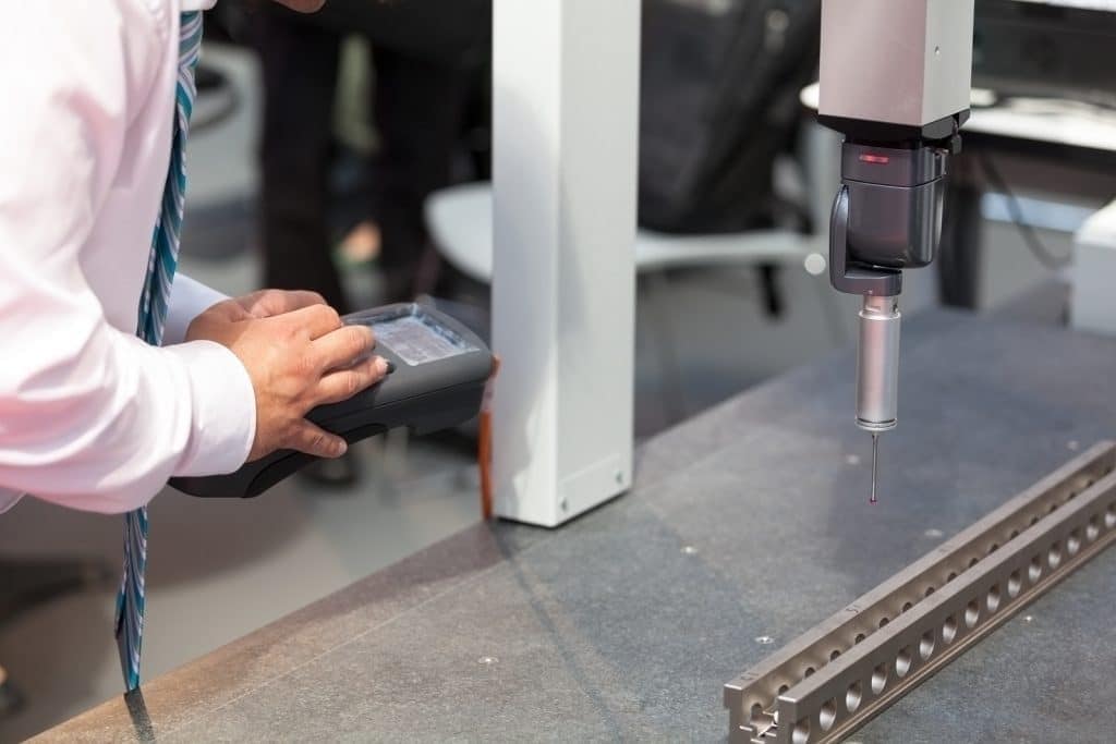
Contact-based Scanning: Coordinate-Measuring Machine
A Coordinate-Measuring Machine (CMM) is an established scanning technology used to obtain a target object’s three-dimensional information. It utilizes a probe or set of probes that can be positioned and moved in three dimensions. The probe is typically equipped with sensors to capture measurements. The CMM systematically moves the probes along predefined paths or through manual control to scan an object’s surfaces. As the probe moves, it collects data points by measuring the object’s coordinates in three-dimensional space. The CMM’s software records the position of each data point relative to a reference point, creating a point cloud or a set of discrete measurements.
A CMM is often used for 3D inspection and quality control in manufacturing and offers high accuracy down to the micrometers. High-end industrial CMMs can be costly to acquire and maintain as they require regular calibration. Compared to non-contact scanning, it is harder to accommodate large-scale items or objects with intricate surface designs. Although research has been done to improve its cycle time, non-contact measurement methods remain more efficient.

Non-contact Scanning Technologies
Non-contact scanning methods can be divided into three subcategories based on the technologies used to capture the 3D information. Triangulation examines the geometric or spatial relationship between the object and the scanner to measure the 3D aspect of the scene. The remaining two subcategories both derive 3D data by analyzing changes in the properties of light observed by the scanner. Time of flight (TOF) is a scanning principle that works best for distant objects, while interferometry is used for precision down to the sub-micrometer level.
Difference Between Contact and Non-contact Sensing Technologies
Non-contact sensing technology allows users to determine the physical properties of a target object at a distance with greater ease and efficiency than contact sensing. Non-contact scanning also reduces the risk of contamination and wear and tear on equipment.
Triangulation Scanning Technologies
The three most widely used triangulation scanners in industrial applications are laser triangulation, stereo vision, and structured light. Both laser triangulation and structured light are active sensors, meaning they send pulses of energy to the scene. Measurements are calculated by analyzing the changes in the reflected energy. In industrial applications, active sensing technologies are often paired with Class II lasers for visibility and safety.
Stereo vision is a passive sensor that views the scene without any external energy-emitting component. A detailed discussion of the principles of laser triangulation continues in this article. Active sensing is generally more robust than passive sensing, as passive sensing is highly dependent on having adequate contrast between the object and its background.
Time of Flight Scanning Technologies
TOF is a method used to measure the distance between the observed object and the scanner by examining the changes in the properties of light. Because of the consistent properties of light, TOF scanners work well for long-range measurements. Direct and indirect TOF are the two types of TOF.
Direct Time of Flight
Direct TOF, also called pulse TOF, works by emitting a pulse of light, usually a laser or an LED light, towards the object and then measuring the time it takes for the signal to return to the sensor. The distance between the object and the sensor can be calculated since the speed of light is known (3 × 10⁸ m/s). Laser-emitting TOF sensors are commonly known as LIDAR (light detection and ranging) and are used to create detailed maps or images of large objects and environments.
Direct TOF is susceptible to ambient light interference and unsuitable for close-range scanning (< 2 m). Distant objects may also weaken signals, making measurements prone to error and noise. Averaging multiple pulses is one remedy to reduce errors in the reading. Direct TOF has a 5 to 20 mm resolution and is suitable for applications within the 10 – 100 m range. Pulse TOF is commonly used in aerial topography measurements. Industrial robotics use information collected from direct TOF scanners to navigate their environment autonomously.
Indirect Time of Flight
Indirect TOF measures distance using continuous laser signals that are amplitude or frequency-modulated. Unlike direct TOF, this method estimates (hence indirect) the distance by calculating the phase shift between the outgoing and return signals rather than measuring the time it takes for the signal to return.
Amplitude modulation (AM) TOF works by varying the amplitude – intensity or brightness – of the light source in a controlled manner. These modulated light signals are directed toward the target object or scene. A sensor captures the reflected or returned laser beam. The scanner measures the time for the signal to complete one full cycle, known as the period. AM TOF offers better resolution at around 3 to 5 mm but at a more limited range than pulse TOF (due to the ambiguity interval problem).
The technique known as frequency modulation (FM) TOF, or frequency modulation continuous wave (FMCW), involves modulating the frequency of laser signals with a particular pattern. As the sensor detects the reflected light, it can measure the frequency shift between the emitted and received light signals. This shift in frequency correlates to the time it took for the laser to travel to the target and back. The accuracy of this method is high, and advanced FM TOF scanners can even achieve measurements within the micrometer range at a distance of 2 m.
Overall, indirect TOF scanning is more resistant to noise and ambient lighting interference, making it more suitable for outdoor usages, such as range sensing and obstacle detection in self-driving cars.
Finally, it is worth noting that other indirect TOF scanning methods, such as Flash LIDAR and range-gated intensity scanning, also exist but are outside this article’s scope. However, further readings can be found here:
Interferometry
While TOF methods are preferred when measuring large objects at a distance (> 2 m), triangulation methods offer the best range resolution where an application falls within a human’s optical depth of field. For measurements requiring high resolution in the sub-micrometer or nanometer level, the interferometry measurement is used.
Interferometry is a technique used to measure distances by analyzing the interference patterns of light. It relies on the principle of interference, which occurs when two or more light waves combine and either reinforce or cancel each other out. The most well-known method is the Michelson interferometer, where a laser beam is emitted and split into two paths. One path serves as a reference, while the other reflects off the target object. The interference pattern arises because the light waves from the two paths have traveled slightly different distances. The resulting interference pattern is either constructive (light waves add up and create a bright pattern) or destructive (light waves cancel each other out and make a dark pattern) and can be analyzed to determine the range or distance to the object.
Interferometry is a highly accurate measurement technique that can achieve nanometer-level precision. It is often used to visualize stress or detect fine deformations for industries such as semiconductors and optics, which require highly accurate measurements. However, it is also extremely noise-sensitive and is only used in a controlled environment.
Mounting Methods of 3D Scanners
3D scanners are frequently used in industrial applications to provide accurate measurements and three-dimensional information about the environment. To enable efficient 3D scanning of large objects on a conveyor belt, many manufacturing processes and warehousing operations opt for a stationary scanning setup using 3D scanners mounted on a gantry or inside a scanning tunnel. For tasks requiring mobility, such as Automated Guided Vehicles (AGVs) or vision-guided robots, 3D scanners can be mounted on railings, mobile robots, or robot end effectors. This provides flexibility in scanning location and ensures seamless scanning operations.
Handheld 3D scanners are more often used in commercial devices for close-range scanning. Tripod-mounted 3D scanners are frequently used for recreating 3D models of artifacts, objects (e.g., orthotics or prosthetics), buildings, or land surveying.
Factors to Consider When Choosing an Industrial 3D Scanner
With all the scanning technologies available, it is important to know what factors to consider to incorporate in an automation project.
The most important three factors are:
- Surface materials
- Range (depth) and resolution (accuracy)
- Scanning speed
Surface Materials
It’s worth noting that the scanning methods mentioned above are highly effective when used on objects that have an uneven surface, as they tend to bounce light off in all directions. Triangulation and TOF methods require light waves to reflect and be seen by the sensor, which requires the target object’s surface to diffuse the incident beam (in most cases, a laser beam), making specular objects harder to scan for these two methods. There are ways to manipulate the scene by adjusting the incident beam’s angle or lighting to mitigate the adverse effect of specular surfaces. Discussing this with an automation professional experienced in machine vision is highly advisable.
Range and Resolution
- Interferometry can detect very fine changes or deviations (sub-micrometers and nanometers) in objects. Their depth of field only spans a few millimeters. Interferometry is suitable for examining high-precision equipment such as optics or electronic components.
- Triangulation scanners are most comparable to a human’s depth of vision, from approximately 0.5 m – 2 m. Though data points are more dispersed at the far end of the active scan zone, the point density (i.e., the distance between two points) is still within millimeters. Most industrial processes fall within the range of laser triangulation scanners. Vision-guided robots also utilize triangulation scanners to complete picking tasks.
- TOF scanners are the furthest-reaching scanning technology mentioned in this article. Although direct TOF has a longer range than indirect TOF, the latter offers better resolution and precision. TOF scanners are suitable for many long-range applications, such as autonomous driving or environment reconstruction.
Scanning Speed
Within the triangulation methods, stereo vision is generally the slowest. It requires the most processing power as it uses two cameras to acquire images of the object from different viewpoints. Structured light can be fast, but some scanners may be suitable only for stationary objects. Laser triangulation is fast and can scan up to 500,000 X, Y, and Z data points per second, accommodating most conveyor belt speeds.
Conclusions
Understanding the workings of basic 3D scanning technologies empowers automation professionals to make informed decisions about implementing the best technology for their manufacturing projects. By utilizing these advanced scanning techniques, industries can enhance quality control, optimize processes, and achieve high levels of accuracy and precision in different automation applications. This contributes to improved productivity, cost, safety, and, ultimately, the development of a more advanced and technologically driven sector.


